Trailer breakaway wiring diagram 3 wire trailer breakaway switch wiring diagram hopkins trailer breakaway wiring diagram rv trailer breakaway switch wiring diagram people today understand that trailer is a vehicle comprised of quite complicated mechanics. A wiring diagram is a streamlined conventional pictorial representation of an electric circuit.
Various connectors are available from four to seven pins that allow for the transfer of power for the lighting as well as auxiliary functions such as an electric trailer brake controller backup lights or a 12v power supply for a winch or interior trailer lights.

You can find out more Diagram below
Trailer wire schematic. This car is designed not just to travel one place to another but also to take heavy loads. When shopping for trailer connectors remember that the male end is mounted on the vehicle side and the female on the trailer side. 4 pin trailer wiring diagram.
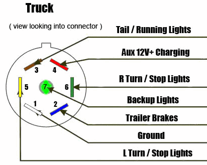
We have an excellent wiring diagram on our website i will provide you a link so you can look at it. If you are looking at the inside of the trailer connector where the wires mount to the terminals starting at the notch at the top and working clockwise. 4 way flat molded connectors allow basic hookup for three lighting functions.
Trailer driving four pin trailer wiring install wiring diagram info. Home trailer towing trailer wiring diagrams trailer wiring diagrams. The following page contains information about trailer to vehicle wiring diagrams including.
It reveals the parts of the circuit as streamlined forms as well as the power and signal connections in between the gadgets. Assortment of electric trailer brake wiring schematic. At a minimum all trailers need at least 4 functions tail lights brake lights left right signals.
A lot of people often struggle with the wiring for the trailer and even after several attempts they still seem not to get it right. Above we have describes the main types of trailer wiring diagrams. When wiring a trailer connector it is best to wire by function as wire colors can vary.
The trailer wiring diagrams listed below should help identify any wiring issues you may have with your trailer. Below is the generic schematic of how the wiring goes. Offroaders staff editor trailer towing.
4 wires will give these functions so the simplest scheme is a 4 pin connector. To connect the electric system of your trailer to the vehicle you will be using special connector. Trailer wiring diagrams 4 way systems.
The most common 4 wire connector is the 4 pin flat connector as shown here. 7 wire trailer circuit 6 wire trailer circuit 4 wire trailer circuit and other trailer wiring diagrams. Right turn signal stop light green left turn signal stop light yellow taillight license side marker brown and a ground white.


0 comments:
Post a Comment