Make this dc cdi for motorcycles. Blackred wire to the cdi 1 of the power coils green wire to the frame earth now this is where it differs.
Whereas dc input cdi units take their power supply from the motorcycle battery.

You can find out more Diagram below
Cdi wiring diagram in motorcycle. Motorcycle wiring in hindi ac cdi. Run a standard red 15a cable to the main fuse 20 30a then to your key ignition. B i aa.
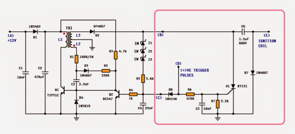
Then run a red from the ve to the starter coil. The circuit on left is a high voltage converter based on a blocking oscillator. The working of the cdi may be found in this article.
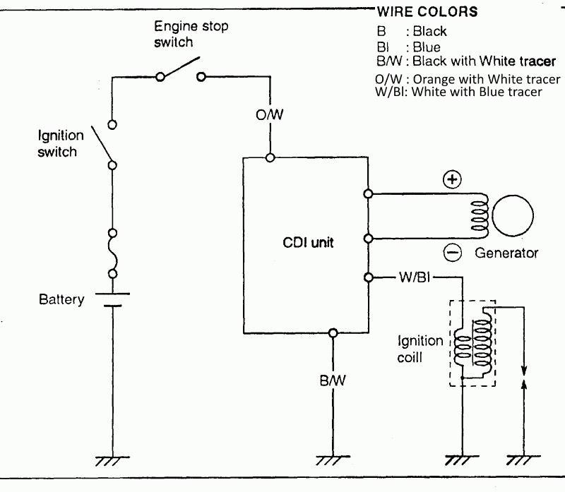
Dc cdi. How to wire 4 pins cdi into 5 pins cdi on motorcycle conversion tagalog. The above diagram is from a honda cb750 custom dual cam bike.
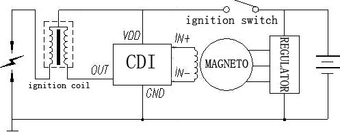
C1 c2 and d1 are dc voltage smoothing components. This is done in heavy duty wire. Motorcycle cdi unit circuit diagram by reza 26 sep 2018 leave a comment therefore we employ a cdi unit or capacitive discharge for collecting and releasing the alternator power in succession order to make cdi capacitor discharge ignition circuit demo the basic cdi circuit best high quality motorcycle cdi unit circuit diagram fit for racing.
I like to start right at the power source the battery. Lots of 70s and 80s bikes will look the same especially the four cylinders. With a fully charged battery and a circuit tester light or an ohm meter trace the voltage 6 or 12 volts from the battery to the first connector.
Typical layout of a dirt bike wiring system cdi this relates more specifically to honda crf50xr50 pit bike clone engines sometimes found in atvs as well. This also simply displays the layout of most motorcycle ignition systems ignore colors. Also be sure to ground your enginegearbox case at one point.
The most important thing to remember is that ac input cdi units take their power supply from the engines stator. Chris custom cycle 147467 views. Acdc cdi.
The components q1 c3 d3 r1 r2 r3 and transformer t1 forms the blocking oscillator. Cdi units come in many different formats. If there is no voltage at that first connector follow the wire back to the battery.
Connect the other side of your starter coil to the starter motor. If you are trying to build a stripped down bike there is a lot going on that you dont need. Motorcycle cdi wiring basics.
Simple motorcycle wiring diagram for choppers and cafe racers. I would say blueyellow wire to the cdi this is the wire that tells the cdi when to spark the other wire should be your neutral light you can see this if you remove your sprocket cover and youll see the wire going to the neutral switch. L1 is the primary coil and l2 is the feedback coil.


0 comments:
Post a Comment