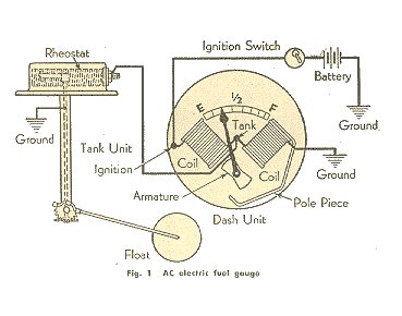
Light bulb if supplied is 12. Obtain 12 volt power from the fuse box using a standard wire and connect it to the positive terminal of the fuel gauge.
Fuel pump wiring for the red circuit is generally going to carry a much higher current than the relay.

You can find out more Diagram below
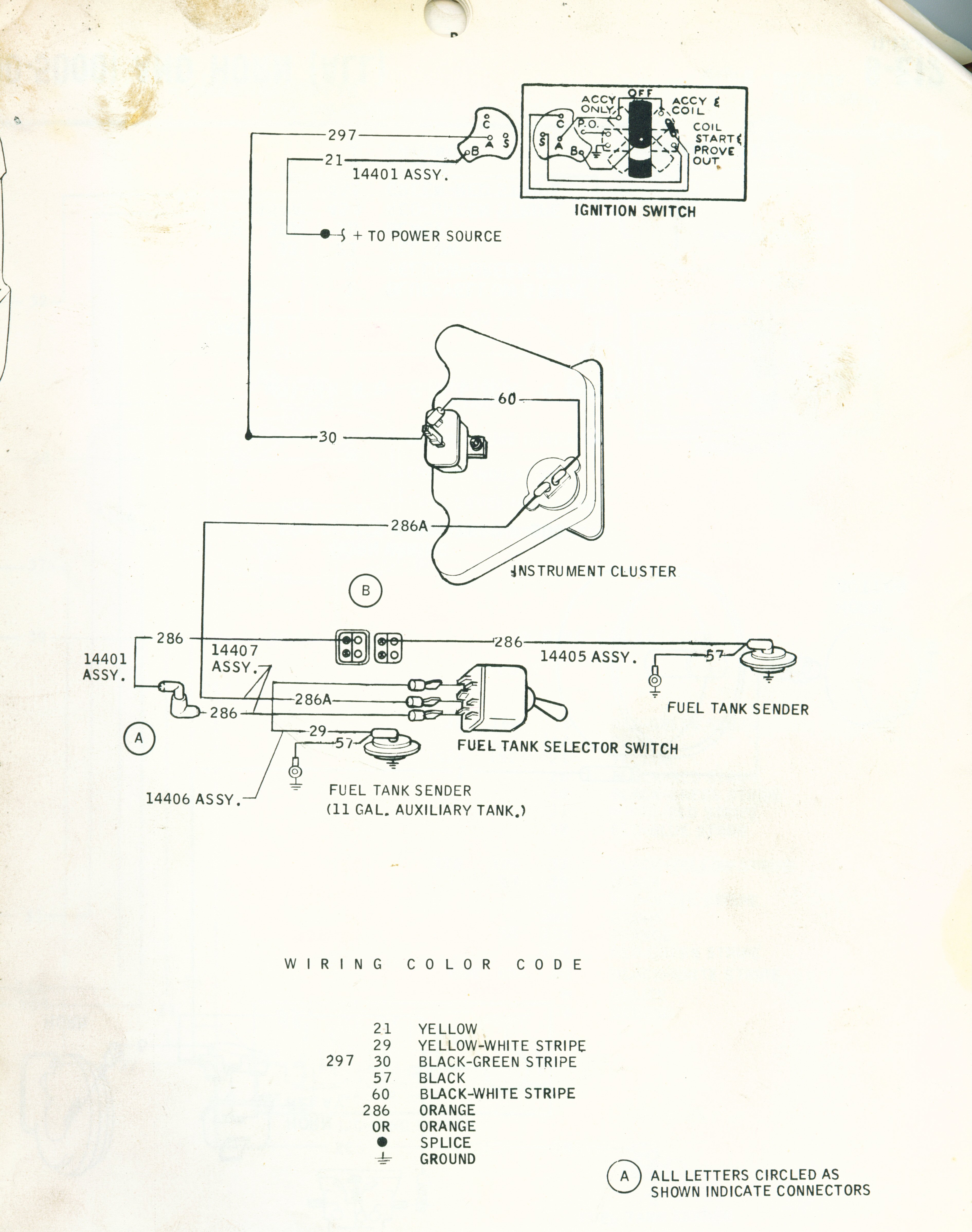
Electric fuel gauge wiring diagram. Align screw holes between gasket mounting plate and tank. Do not over tighten nuts on back of gauge. Always disconnect battery ground before making any electrical.
Next connect a wire from the float on the fuel tank to the negative terminal of the fuel gauge. Electric sending unit to fuel gauge wiring diagram. Basic safe electric fuel pump wiring diagram this is the basic wiring diagram for safe electric fuel pump wiring.
Pressure andor fuel gauge are contained herein. 0 515 012 123 electric gaugesp65. 18 gage wire from fuel tank to gauge.
See diagram for details 6. Install the new gauge reconnect the wiring and turn on the power. Fuel sending unit wiring diagram volovetsfo.
10 gauge wire or larger must be used. Fuel gauge check the wiring diagram that comes with the kit and mark the back of the new fuel gauge with symbols for each post. S for the sender g or for the ground and i for the ignition.
Wire a fuel gauge by first disconnecting the old dysfunctional unit to replace it with a new one. Electric fuel sender wiring diagram wire center wiring diagram. It shows the parts of the circuit as simplified shapes and the power as well as signal links between the devices.
There is a lot of confusion and misunderstandings about them. Were going to show you how to install it and wire it up the correct way. Want an electric fuel pump to last forever and work right.
Install your electric fuel sender gently inserting float arm into tank followed by sending unit. Connect sender wire from fuel gauge to the threaded screw terminal on sender. The diagram is color coded per circuit and only a few things may need to be said.
Ok lets talk about electric fuel pumps. How to do it right. Use is restricted to 12 volt negative ground electrical systems.
If a new hole is drilled in the firewall a grommet is recommended. If you are not familiar with proper brake system bleeding. Automotive wiring diagram worksheet inspirationa fuel gauge sending.
Do not deviate from assembly or wiring instructions. A wiring diagram is a simplified standard pictorial depiction of an electrical circuit. So use a larger gauge wire for lower voltage drop.
Installation instructions short sweep electric gauges 2650 1079 00 rev. Fuel gauge sending unit wiring diagram collections of 36 fuel gauge wiring diagram chevy types of diagram. Variety of marine fuel gauge wiring diagram.
Installation instructions full sweep electric pressure gauges 2650 1134 00 rev. For fuel pressure gauge. D sender good engine ground grommet 12v connection red.


0 comments:
Post a Comment